The idiot in question being... me!
It's been ages since I did any real electronics. Most of my work involves software and pre-assembled bits of kit. I thought that it was time I reacquainted myself with the joys of electricity :-)
Because I'm fundamentally lazy, I purchased the all-in-one Raspberry Pi 2 kit from Vilros.

Lots of LEDs, some buttons, a nice case, all the cables, resistors, and all sorts of bits and bobs. Including a breadboard!
What's A Breadboard?
I remember - from school - that a breadboard is a.... thing... that lets you... electricity?
Honestly, it wasn't until I saw this diagram from Adafruit that it all finally clicked into place:

Aha!
The kit comes with a T-Shaped Cobbler which fits onto the breadboard and means you have a neatly labelled system with fewer wires running about the place.

I followed a sample tutorial on how to wire in an LED to be permanently on. Basically +3.3v → long leg of LED. Short leg of LED → 330Ω resistor → Ground.
Ok, that was easy. Now lets make it flash on command!
The wiring is fairly similar, but we use a controlable GPIO pin instead.
GPIO pin 21 → long leg of LED. Short leg of LED → 330Ω resistor → Ground.
Here's what it looks like:

And here's the Python code to switch it on, then off.
import RPi.GPIO as GPIO
GPIO.setmode(GPIO.BCM)
led = 21
GPIO.setup(led, GPIO.OUT)
# Switch on
GPIO.output(led, 1)
# Switch off
GPIO.output(led, 0)
Wooo!
Ok, so, next thing - how to get information in to the Pi?
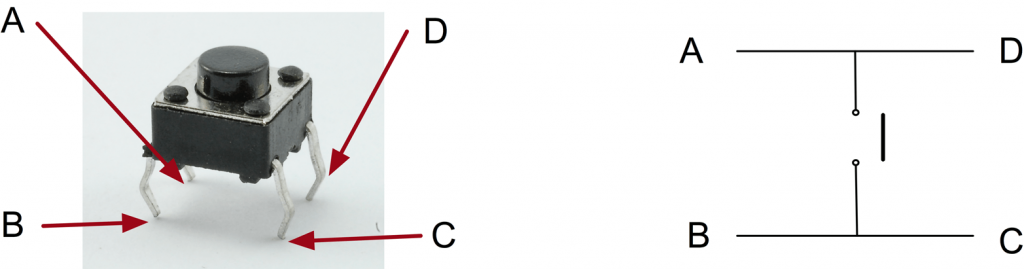
I was confused about exactly how the push switch worked - why were their four pins?
I read the O'Reilly Raspbery Pi Tutorial and became enlightened.
So, lets create a thingumy which lights up an LED when a button is pressed.
The LED will be the same as the above. The button will be wired as: GPIO pin 19 → Button A. Button B → Ground.

And the code is:
import RPi.GPIO as GPIO
import time
GPIO.setmode(GPIO.BCM)

# Pin 19 will sense for button pushing
button = 19
GPIO.setup(button, GPIO.IN, pull_up_down=GPIO.PUD_UP)

# The LED
led = 21
GPIO.setup(led, GPIO.OUT)

while True:
    input_state = GPIO.input(button) # Sense the button
    if input_state == False:
        print('Button Pressed')
        time.sleep(0.2)
        # Switch on LED
        GPIO.output(led, 1)
    else :
        # Switch off LED
        GPIO.output(led, 0)
I'm not entirely sure why if input_state == False: is the logic for the button being pressed. Seems like it ought to be True, no? Anyway, there's a long discussion about all the ways sensors can be read on the raspberry-gpio-python pages.
Well, there you have it. An utterly simple guide to getting started. I just hope future-me finds this useful!
13 thoughts on “Idiot's Guide To Getting Started with Raspberry Pi's GPIO Pins”
Hey, just wanted to let you know....that I did actually find this simple post rather useful in more than one way! Cool beans! What's up with part 2? ?
Alan Forsyth
Thanks for that Graham - I have a similar background to you, so just dabbling again in electronics for the first time since school days. I picked up the same kit for the same reason (great minds and all that), but was unsure which way round to connect the GPIO cable on the PI. A quick check with my old multimeter confirmed that it was the way one would expect (i.e. cable not running over the PI), and along with your breadboard pic above, there were no mishaps! Anyway, the experiments above worked well, and I followed the instructions in the PDF on the Vilros website (shown on this product's page) to set up a flashing LED, etc. I think the reason that pushing the switch sets a logical 'FALSE' is due to it being connected to ground ('0'), so connecting the GPIO circuit to ground is thus a FALSE input.
Anyway, thanks again - it was reassuring to see your clear pics as I'm taking my first steps in this direction.
Alan Forsyth
Sorry Terence for the name mixup - haven't had my coffee yet this morning!
Greg
Hey Terence. Thanks for the super easy tutorial! I got a similar kit for Christmas (though mine has the camera module) and have been pulling my hair out trying to get GPIO/led control to work. When I did not use the T Cobbler and used the wires to connect the breadboard to the ribbon cable (which is connected to the r-pi), the commands did not work. The led did go on when connected directly to the first pin (3.3v). I followed your instructions exactly and everything works! Guess I'll have to go back to see what I did wrong.... Anyway, thanks for the sanity check!
Neil
YES! Just what I've been looking for. I opted to move the time sleep under the GPIO.output. Only noting this hear because I was thinking my light wasn't working. I was rapidly clicking... and then I noticed the sleep function... was sleeping, while I let go of the button and the state changed.
Hunter
I noticed that if you keep the button pressed down the message "Button Pressed" repeatedly comes up. Is there a way to make it only come up once?
PiFace
Thank you a lot! I got a Raspberry Pi for Christmas and didn't really know what to do with the breadboard, so your guide was exactly what I needed. The world needs more of these easy to understand tutorials.?
I’d gotten as far as using the GPIO for output, but had no clue how to use the button. Thank you for a very clear tutorial.
Mary
This is exactly what I've been looking for - thank you! Do you have any more easy to follow projects like this one - I have all sorts of 'stuff' but don't know what to do with it all - thought I'd figure it out on my own but most sites use acronyms and I spend so much time searching for the meaning of the acronyms that I loose interest.
@edent
Glad you enjoyed the post. I have a series of Raspberry Pi posts - of varying difficulty - at https://shkspr.mobi/blog/tag/raspberry-pi/
Hope you find something that suits you.
Mary B
Thank you. I’m finding all sorts of good stuff!
Joe
Hi all. im a beginner at this raspberry pi stuff too. Question, When connecting l LED strips directly to the Gpio pins, Can a program such Hyperion still be used? Is the a way to tell hyperion which pins i Placed the RGB pins into? I'm able to turn the Lights on by using a RasPii phone app by switching a gpio pin to Out.
Trackbacks, Pingbacks, and Boosts
[…] I managed to copy a code that is shown on this website. That guide includes a breadboard setup and I copied that too. So, by now, I got my first program […]